

Product Details
Place of Origin: China
Brand Name: AIP
Model Number: AIP89XX
Payment & Shipping Terms
Minimum Order Quantity: 1 set
Price: Negotiable
Packaging Details: Wooden case
Delivery Time: 45 working days
Supply Ability: 50 sets per month
Product: |
Air Conditioner Motor Testing Machine |
Test: |
Hipot/ IR/ Surge/ Resistance/ Rotation/ Power/ Current/ Stall |
Test Time: |
8s |
Application: |
Motor Production Line |
Service: |
Remote Control Service Suppot |
Warranty: |
1 Year |
Product: |
Air Conditioner Motor Testing Machine |
Test: |
Hipot/ IR/ Surge/ Resistance/ Rotation/ Power/ Current/ Stall |
Test Time: |
8s |
Application: |
Motor Production Line |
Service: |
Remote Control Service Suppot |
Warranty: |
1 Year |
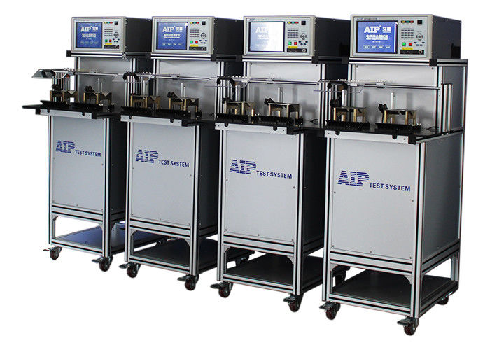
Air Conditioner Motor Testing Machine / Acceptance Testing Of Electric Motor
1. Tested product: air conditioner motor
Application: air conditioner production
![]()
![]()
2. Product features
High performance: compatible to test Hipot, insulation resistance, surge, winding resistance, rotation, no-load and stall. Easy-to-maintain: support intelligent self-diagnose, remote control failure diagnosis and online software upgrading.Modular design: independent test module design, all the test items are separately. Multiple languages are available to meet the requirements of customers all around the world.
3. Technical specifications
| Insulation resistance | |
| output voltage setting range/precision | DC 500V/1000V ±(2%×setting value+10V) |
| insulation resistance testing range/precision |
1~500MΩ ≤100MΩ:±(3%×setting value+0.5MΩ) ;>100 MΩ:±(5%×setting value+5MΩ) |
| insulation resistance alarm setting range | Max: 0~500MΩ; Min: 1~500MΩ |
| test time range/resolution | 0.5~999s 0.1s/step |
| AC Hipot | |
| test time range/resolution | 0.5~999.9s 0.1s/step |
| Output voltage setting range and precision | AC 200~3000V ±(2%×setting value+10V) |
| breakdown current testing range/precision | 0.10~20.00mA ±(2%×display value+0.05 mA) |
| Hipot current presetting alarm range | Max:0.10~20.00mA;Min:0.00~20.00mA |
| Surge | |
| output voltage setting range/precision | 500~3000V ±(3%×display value+8V) |
| sampling frequency | 100MHz |
| waveform comparison |
area, area difference, corona and phase 3 waveforms displayed in the testing interface |
| DC winding resistance test | |
| testing range and precision | 10.0mΩ~20KΩ ±(0.3%×display value+3 words) temperature compensation can be set. |
| test time range/resolution |
0.5~999s 0.1s/step
|
| temperature compensation function | Yes |
| temperature probe/range | DS18b20 -10.0℃~+50.0℃ |
| precision | ±0.5°C(range: -10℃~+50℃) |
| Low voltage start | |
| voltage testing range and precision | AC:30~500V ±(0.5%×display value+1 words) |
| current testing range and precision | AC:0.02~5.0A ±(0.5%×display value+2 words) |
| power testing range and precision | 0.6-1500W ±(0.5%×display value+5 words) |
| Stall | |
| voltage testing range and precision | AC:30~500V ±(0.5%×display value+1 word) |
| current testing range and precision | AC:0.02~5.0A ±(0.5%×display value+2 words) |
| power testing range and precision | 0.6-1500W ±(0.5%×display value+5 words) |
| No-load | |
| voltage testing range and precision | AC:30~500V ±(0.5%×display value+1 word) |
| current testing range and precision | AC:0.02~5.0A ±(0.5%×display value+2 words) |
| power testing range and precision | 0.6-1500W ±(0.5%×display value+5 words) |
| Direction of rotation | |
| rotation | CW, CCW, still |
4. Test procedures:

